Dose and image quality
Balance optical efficiency with contrast, feature transfer, edge behavior, and usable depth of focus.
PAO develops maskless exposure optical engines from source coupling and DMD illumination through projection, focus, calibration, and production-ready optomechanics.
For PCB, advanced packaging, microfabrication, and application-specific direct imaging.
Pixel mapping, source etendue, DMD state contrast, projection NA, distortion, focus, thermal load, scan or stitching strategy, and resist response all affect the usable process window.
Balance optical efficiency with contrast, feature transfer, edge behavior, and usable depth of focus.
Control distortion, magnification, focus surface, pixel mapping, stitching, and stage-to-optics calibration.
Manage source heat, spectral stability, contamination, DMD loading, and alignment drift over duty cycle.
Best for teams ready to close process decisions around dose, mapping, source spectrum, and calibration into one controlled optical-engine program.
Feature size, dwell, dose, resist, and throughput are known, but source-to-projection coupling and mapping strategy are still open.
Field roll-off, stitching mismatch, distortion drift, or thermal-induced drift is reducing repeatability during prototype runs.
A bench build exists, but procurement is blocked by missing tolerances, calibration maps, test conditions, and issue-tracking format.
| Input condition | Key metric | Design choice | Risk if unresolved |
|---|---|---|---|
| Feature and throughput target | Minimum resolvable feature, cycle time, dose uniformity | Line-imaging versus projection mode, NA, zoom strategy, source and duty settings | Throughput can increase while critical pitch quality degrades. |
| Source and process chemistry | Spectral response, conversion efficiency, contrast, aging | LED or LD architecture, band set, thermal control, monitoring points | Incorrect source strategy can hide process drifts and overpromise stability. |
| Calibration and mapping path | Pixel mapping error, distortion residual, registration repeatability | Mapping grid, correction order, distortion model, reference artifact | Acceptance may fail during stage transitions or production setup changes. |
| Procurement and production readiness | Supplier lead time, qualification scope, test method consistency | Controlled BOMs, drawings, optical/mechanical package, release criteria | The prototype cannot be converted to reliable pilot manufacturing. |
These records describe documented engineering experience or the evidence plan PAO uses for new work. They do not imply that prior-employer programs were PAO customer engagements.
The optical engine is developed against the actual exposure process rather than treated as an isolated projection lens.
Define a technical work packageFeature target, resist sensitivity, pixel scale, magnification, overlap, throughput, and focus allocation.
LED or laser-diode coupling, spectral selection, fly-eye or light-pipe homogenization, pupil fill, and radiometry.
Device format, tilt geometry, illumination angle, contrast paths, window effects, cooling, and mechanical interface.
Magnification, NA, modulation transfer, distortion, telecentricity, focus surface, and chromatic control.
Pixel-to-stage mapping, geometric correction, uniformity correction, autofocus interface, and image verification.
Precision mounting, alignment sequence, tolerance model, optical acceptance, and supplier-ready release.
These configurations demonstrate available delivery pathways. PAO defines the production requirement, system interfaces, calibration, verification, and changes needed for the intended application.
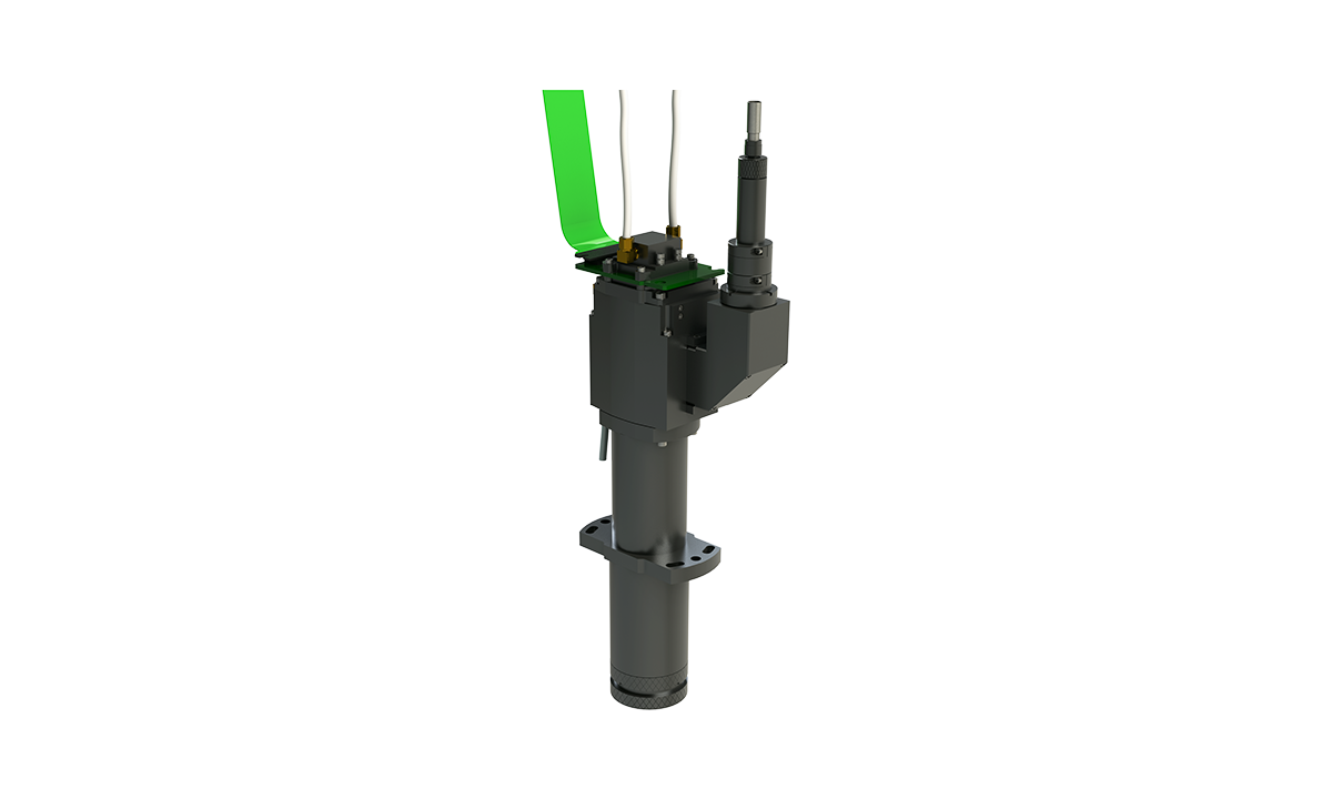
A configurable optical-engine starting point for line-layer exposure. PAO adapts the architecture, interfaces, calibration, and acceptance plan to the customer's process.
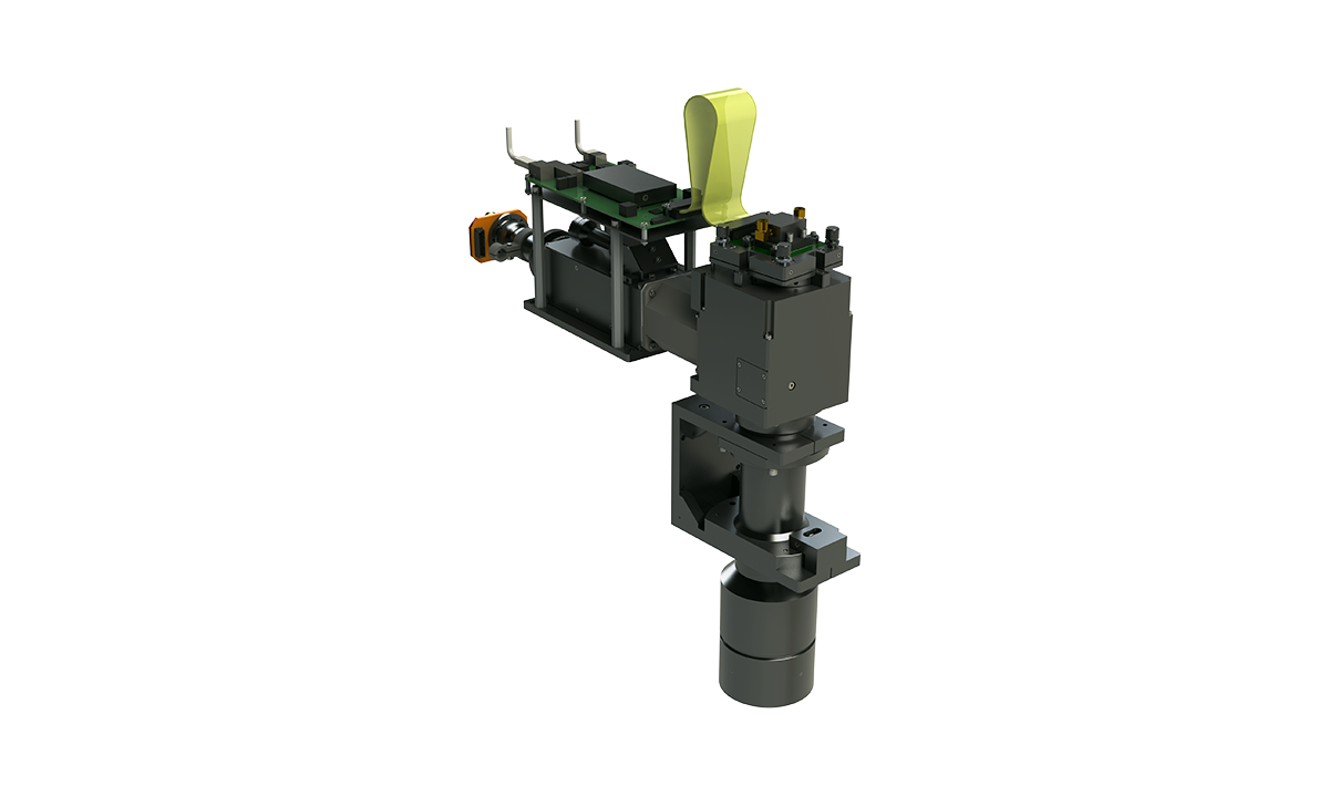
A source-flexible engine architecture for solder-mask and substrate applications requiring process-specific spectral and thermal design.
Representative capability is shown with the context needed to qualify it. Program requirements control the final architecture and acceptance values.
Projection architectures for fine line and space patterning with controlled field mapping and focus.
Mixed-wavelength or application-tuned UV delivery for photosensitive solder-mask processes.
Maskless exposure for substrates, redistribution-related processes, and specialized microfabrication steps.
Purpose-built DMD engines for research, additive, patterning, curing, and machine-integrated applications.
The values above describe representative platform envelopes. Feature transfer depends on resist, substrate, dose, contrast, focus, motion, calibration, and acceptance method; final performance is defined and verified per program.
The exact package follows the program stage and scope. Assumptions, interfaces, decisions, and acceptance evidence remain visible.
Source-to-substrate optical layout, power budget, pixel budget, interfaces, and risk register.
Source coupling, homogenizer, relay, pupil control, filters, thermal inputs, and irradiance model.
Lens prescription, magnification, MTF, distortion, telecentricity, focus, and tolerance analyses.
Mapping, distortion and uniformity correction, focus procedure, artifacts, and data products.
DMD, optical, mechanical, thermal, stage, controls, and service interfaces.
Build oversight, alignment, test correlation, issue closure, and configuration-controlled release.
PAO leads the technical work, coordinates specialized fabrication and production resources under the project quality process, and keeps responsibility for requirements, interfaces, evidence, and issue closure clear.
Define the system boundary, decision to be made, current evidence, constraints, and confidentiality path.
Create measurable requirements, interface assumptions, performance budgets, and a ranked technical risk register.
Compare viable concepts and retire the highest-risk assumptions with analysis, breadboards, or targeted tests.
Develop controlled optical, mechanical, calibration, test, and supplier-ready documentation.
Support procurement, assembly, alignment, test correlation, root cause, and evidence-based iteration.
Close acceptance criteria, configuration, supplier questions, manufacturing issues, and production handoff.
Either scope is possible. For lower integration risk, PAO typically defines source, illumination, DMD, projection, optomechanics, calibration, and test as one controlled subsystem.
Potentially, but coatings, materials, focus, source etendue, detector response, and resist sensitivity must be evaluated together. A wavelength choice should be treated as a system trade, not a component substitution.
Pixel scale, projection NA, aberrations, contrast, focus, vibration, dose, resist behavior, substrate flatness, motion, and image processing all contribute. PAO establishes a traceable budget and verification method for the target process.
Send the feature, field, resist, wavelength, dose, working distance, and throughput targets available today. Unknowns can be handled as explicit trades.